| Figure 1: |
Power and Ground

|
| Figure 2: |
MIL and DLC

|
| Figure 3: |
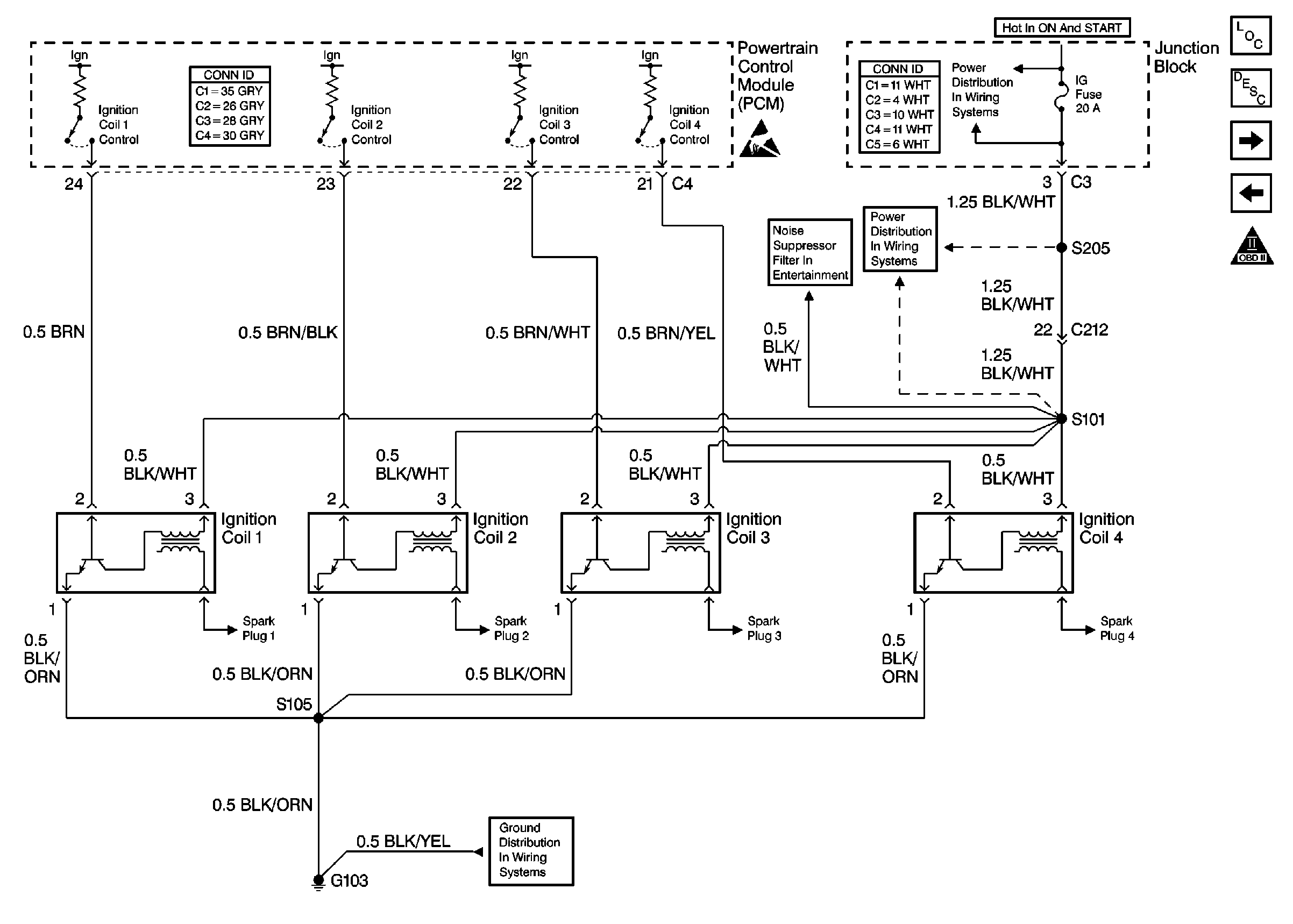
Ignition System
|
| Figure 4: |
CMP and CKP Sensors

|
| Figure 5: |
Fuel Supply System

|
| Figure 6: |
Fuel Injectors

|
| Figure 7: |
Engine Data Sensors

|
| Figure 8: |
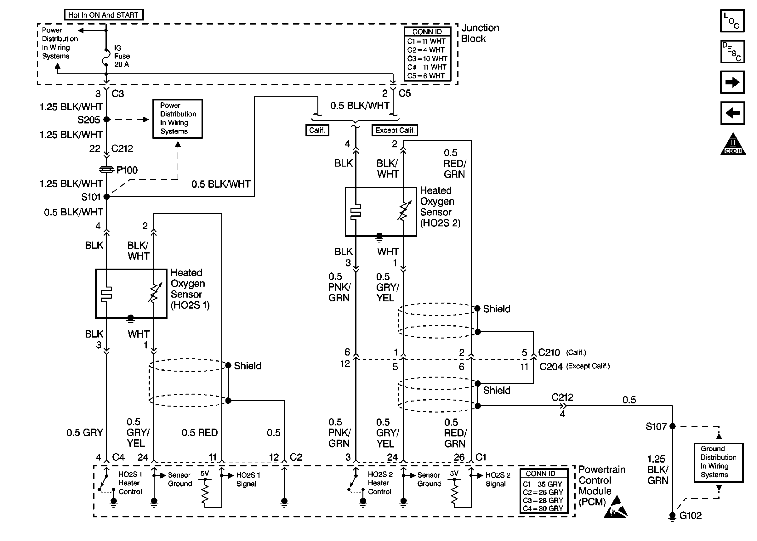
HO2S Sensors
|
| Figure 9: |
IAC, MAF Sensor and VSS

|
| Figure 10: |
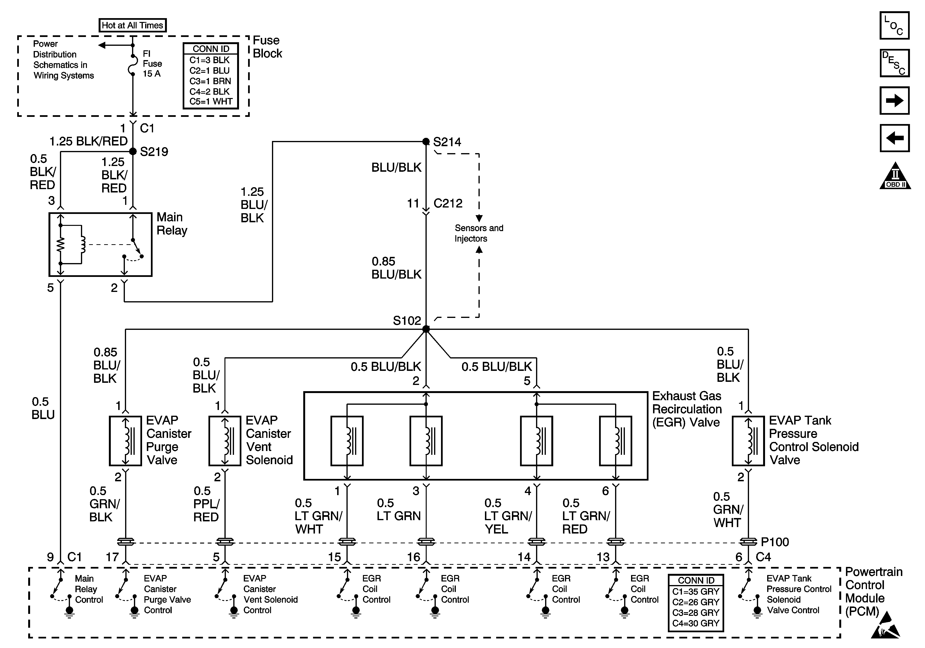
EGR Valve and EVAP Controls
|
| Figure 11: |
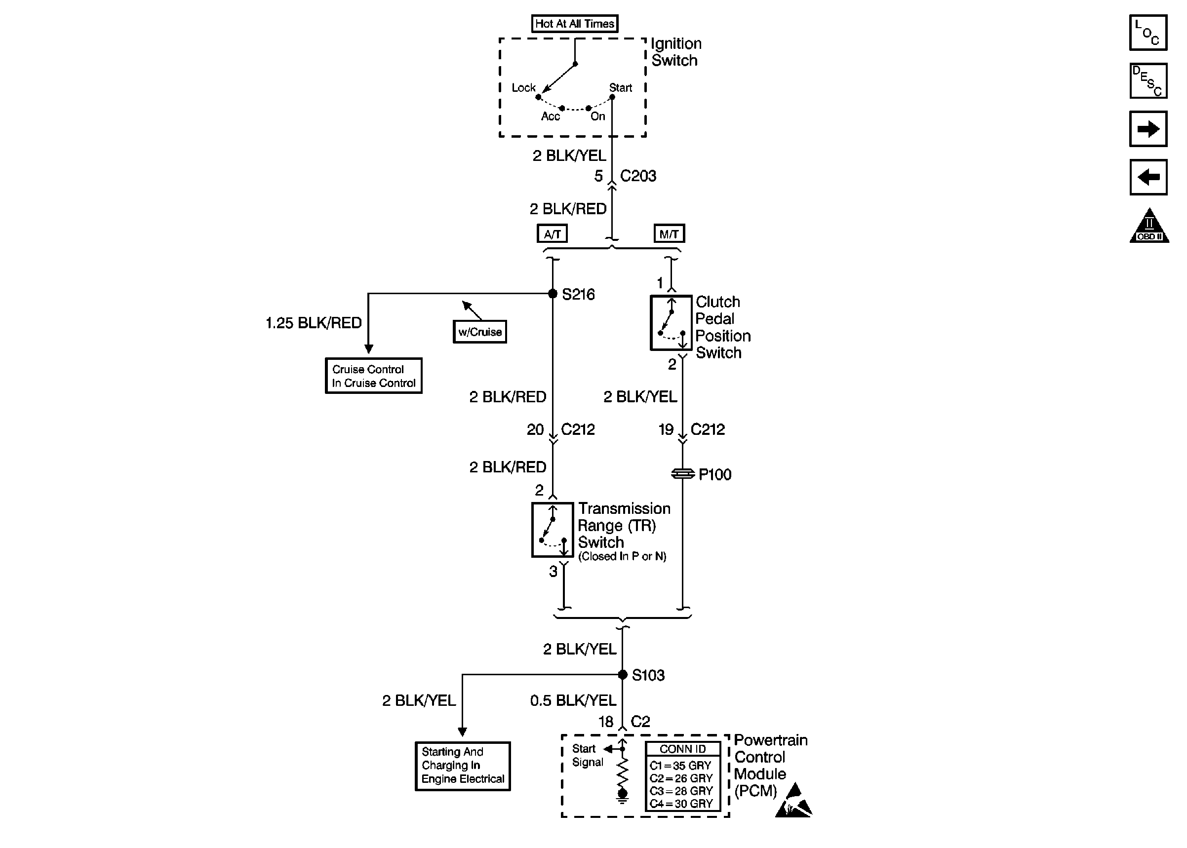
TR Switch and CPP Switch
|
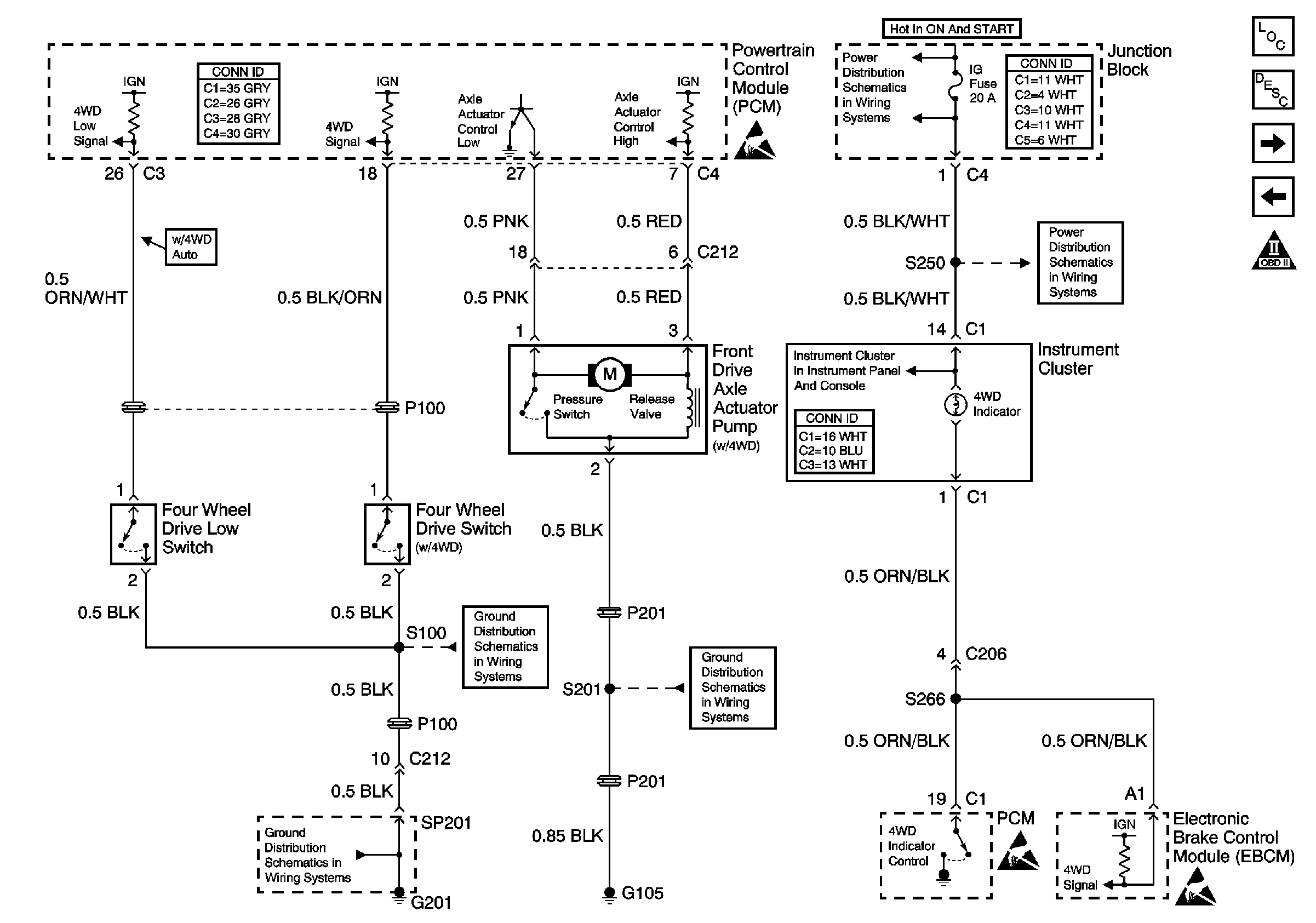
| Figure 12: |
Four Wheel Drive Inputs/Outputs
|
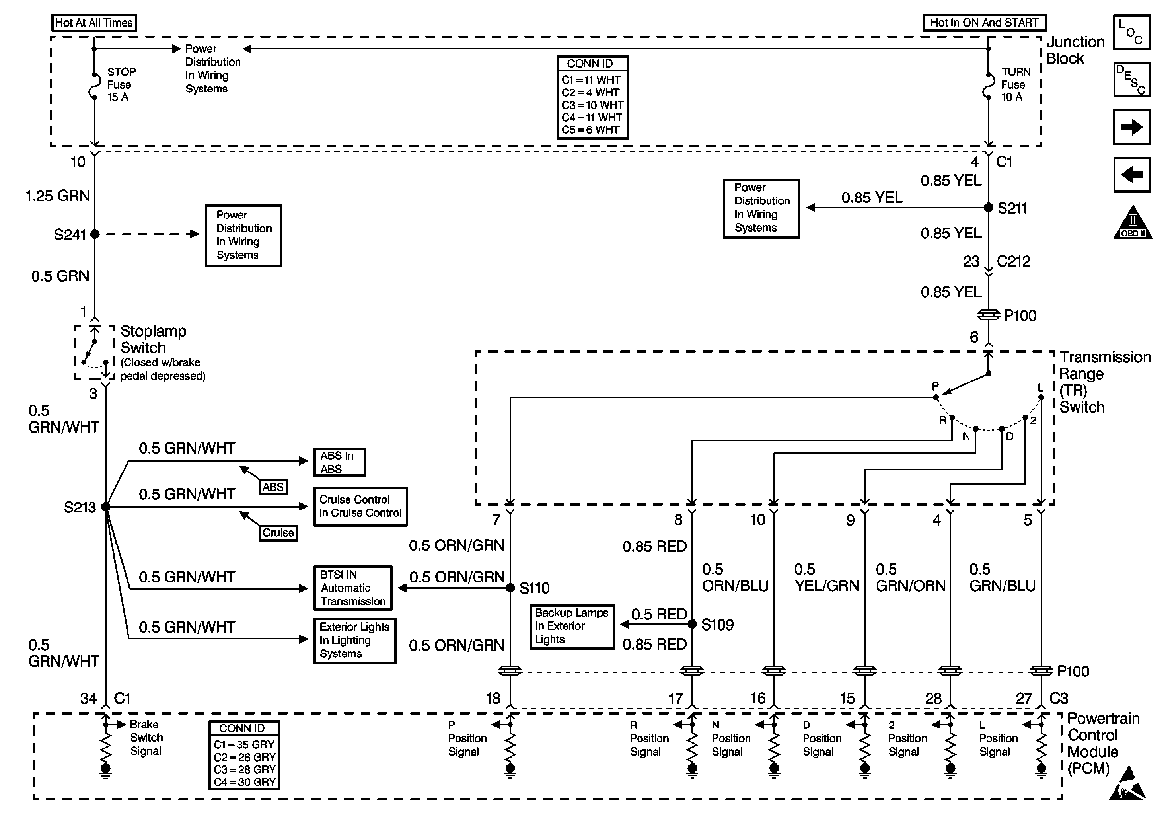
| Figure 13: |
TR Switch Position and Stoplamp Switch Inputs
|
| Figure 14: |
A/T Speed Sensors and A/T Solenoids

|
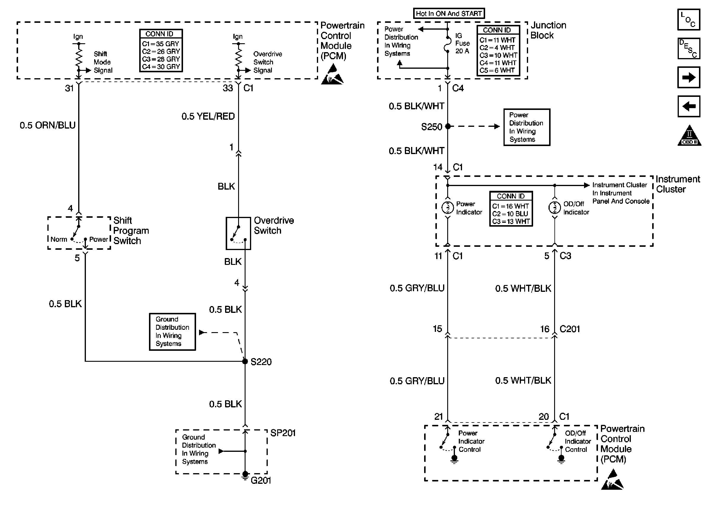
| Figure 15: |
A/T Controls and Outputs
|
| Figure 16: |
A/C Controls and Idle-Up Signals

|


