- Relieve the fuel pressure. Refer to
Fuel Pressure Relief
in Engine Controls.
Caution: Unless directed otherwise, the ignition and start switch must be in the OFF or LOCK position, and all electrical loads must be OFF before servicing
any electrical component. Disconnect the negative battery cable to prevent an electrical spark should a tool or equipment come in contact with an exposed electrical terminal. Failure to follow these precautions may result in personal injury and/or damage to
the vehicle or its components.
- Disconnect the negative battery cable.
- Raise and support the vehicle. Refer to
Lifting and Jacking the Vehicle
in General Information.
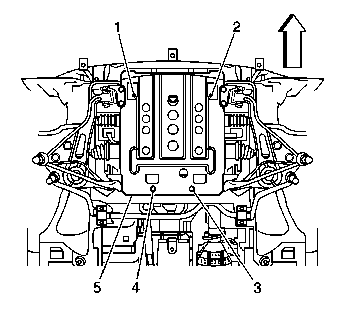
- Remove the front skid plate (5) from the vehicle, if equipped.
- Drain the engine cooling
system. Refer to
Cooling System Draining and Filling
in Engine Cooling.
- Drain the engine oil.

- Remove the automatic
transmission fluid cooler lines (1) from the radiator on automatic
transmission equipped vehicles. Cap the open lines to prevent leakage.
- Remove the flywheel cover.

- Remove the torque converter
bolts on automatic transmission equipped vehicles. Use the J 35271
in order to lock the flywheel (1).
- Support the transmission.
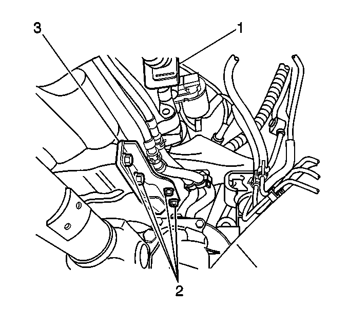
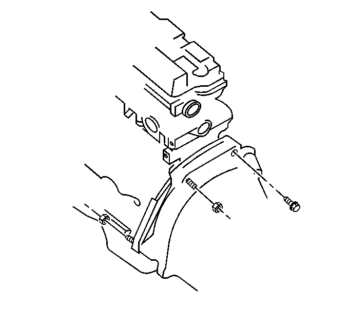
Remove the 4 bolts and the right side engine-to-transmission support
bracket (3).
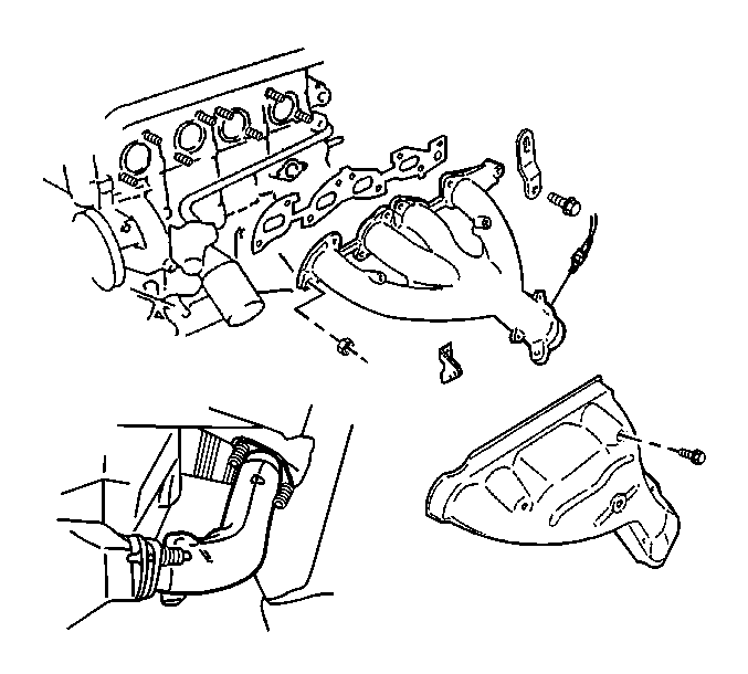
- Remove the 2 bolts
and separate the front pipe assembly from the exhaust manifold on vehicles
not equipped with the PUP catalytic converter.
- Lower the vehicle.
- Remove the hood from the vehicle. Refer to
Hood Replacement
in Body Front End.

Important: The vehicle should be supported on a hoist prior to removing the strut
tower brace. This will facilitate removal and installation of the brace.
- Remove the 6 bolts and the strut tower brace. Refer to
Front Suspension Support Brace Replacement
in
Front Suspension.

- Remove the 3 nuts
and separate the front pipe assembly from the exhaust manifold on vehicles
equipped with the PUP catalytic converter.
- Remove the engine block-to-catalytic converter support bracket.

Important: Do not discharge the A/C system nor remove the refrigerant lines from
the compressor.
- Remove the 3 bolts (1) and the A/C compressor, if equipped,
from its bracket and position aside. Refer to
Air Conditioning Compressor Replacement
in HVAC Systems with A/C Manual.
- Remove the 4 bolts (2)
and the A/C compressor bracket, if equipped. Refer to
Compressor Mounting Bracket Replacement
in HVAC Systems
with A/C Manual.
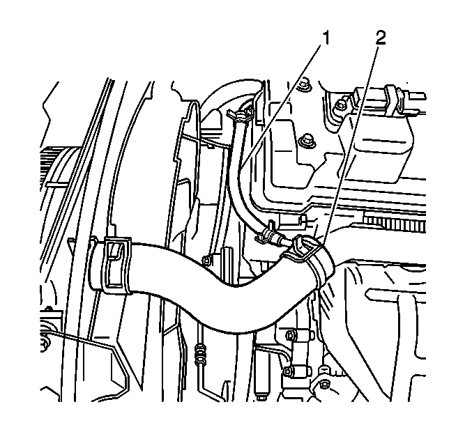
- Remove the upper radiator
hose (2) from the vehicle.
- Remove the lower radiator
hose (1) from the vehicle.
- Remove the radiator overflow hose from the radiator.
- Remove the 4 radiator shroud clips.
- Remove 1 bolt from each side of the radiator upper support.

- Lean the fan shroud toward
the engine and lift the radiator up and out of the vehicle.

- Remove the four fan mounting
nuts (1). Use a second wrench to hold the fan shaft.

- Remove the fan and the
fan shroud.
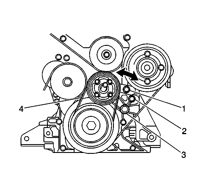
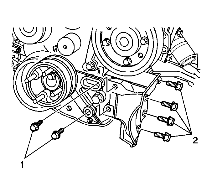
- Loosen the adjusting bolt (1)
and the pivot bolt (3).
- Remove the tension on the fan belt by rotating the tension bolt (2)
counterclockwise.
- Remove the fan belt.
- Remove the 2 tensioner mounting bolts (1,3) and
the tensioner.

- Rotate the belt tensioner
clockwise and remove the accessory drive belt.
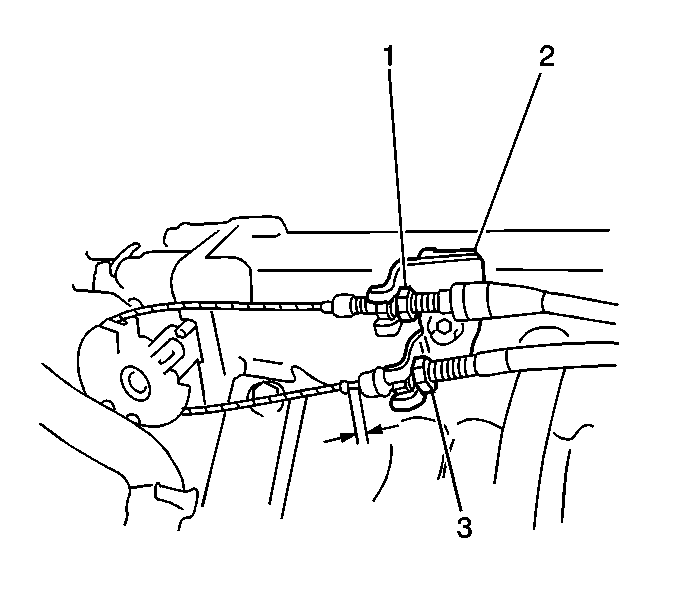
- Remove the bolt and the
throttle cable bracket (2) from the intake manifold.
- Remove the cables from the throttle body bellcrank and position
aside.
- Remove the power steering pressure and return lines from the power
steering pump and position aside. Cap the open lines to prevent leakage.
- Disconnect the intake air temperature (IAT) sensor connector.
- Disconnect the mass air flow (MAF) sensor connector.
- Remove the air cleaner assembly. Refer to
Air Cleaner Assembly Replacement
in Engine Controls.

- Remove the heater hoses
from the heater core. Mark the location of the inlet and outlet hoses
for correct installation.

- Disconnect the fuel feed
and return hoses (9). Label the feed and return hoses for correct
installation.
- Disconnect the following electrical connectors:
| • | The fuel injector wiring harness (3) |
| • | The throttle position sensor (TPS) (8) |
| • | The manifold absolute pressure (MAP) sensor (11) |
| • | The idle air control (IAC) valve (6) |
| • | The exhaust gas recirculation (EGR) valve (1) |
| • | The engine coolant temperature (ECT) sensor (2) |
| • | The EVAP canister purge valve (7) |
| • | The heated oxygen sensor 1 (HO2S1) |
| • | The camshaft position sensor (CMP) |
| • | The power steering pressure (PSP) switch wire |
| • | The oil pressure switch wire |
- Remove the bolt and the ground wires from the intake manifold (10).
- Remove the EVAP canister purge hose from the intake manifold.
- Remove the wiring harness from the retaining clamps.
- Remove the brake booster vacuum line from the intake manifold.

- Disconnect the starter
solenoid electrical connector.
- Remove the nut and the battery positive cable (3) from
the starter solenoid.
- Remove the 2 bolts (1) and the starter motor. Refer
to
Starter Motor Replacement
in Engine
Electrical.
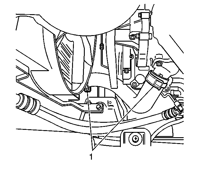
- Disconnect the crankshaft position sensor (CKP) (2) connector.
- Remove the cylinder block-to-transmission
bolt and nuts.
- Remove the 2 nuts
from the top side of the engine mounts.
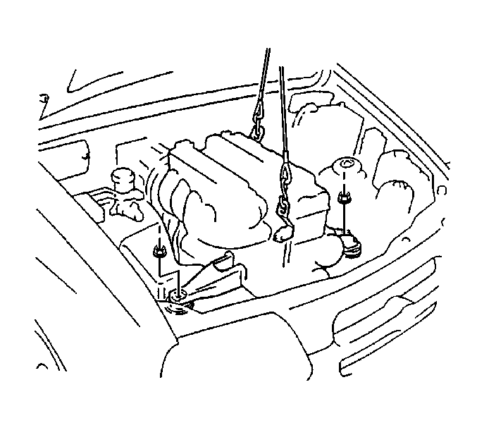
- Install an engine hoist to the engine.
Important: Before lifting the engine, ensure that all of the hoses, pipes, electrical
wires and cables are disconnected from the engine and positioned aside.
- Remove the engine assembly from the vehicle by sliding the assembly
toward the front side of the engine compartment. Carefully lift the engine
assembly from the vehicle verifying clearance on all sides.
- Remove the pressure plate assembly and the clutch disc on manual
transmission equipped vehicles. Refer to
Clutch Assembly Replacement
in Clutch.
- Mark the flywheel-to-engine position.
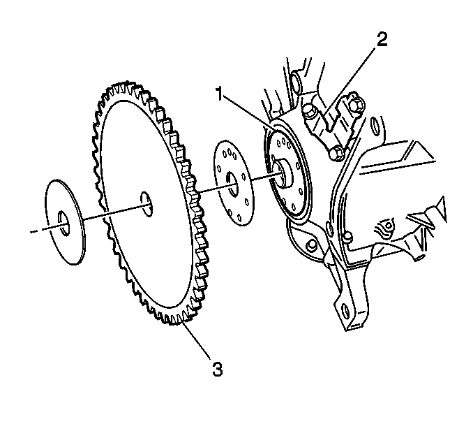
- Remove the 8 bolts and
the flywheel (3) from the crankshaft.
- Place the engine assembly onto the J 36854
.
- Remove the engine hoist.
- Remove the crankshaft position sensor.
- Install the engine hoist.
- Remove the engine assembly from the J 36854
.
Notice: Apply the proper amount of the sealant to the fastener when assembling
this component. Excessive use of the sealant can prohibit the component from
being assembled properly or allow the fastener to loosen. A component or fastener
that is not assembled properly can loosen or fall off leading to extensive
engine damage.
- Install the crankshaft position sensor.
- Align the flywheel-to-engine marks and install the flywheel (3).
- Apply GM P/N 12345493
(Canadian P/N 10953488) or the equivalent, to the flywheel retaining bolt
threads.

Notice: Use the correct fastener in the correct location. Replacement fasteners
must be the correct part number for that application. Fasteners requiring
replacement or fasteners requiring the use of thread locking compound or sealant
are identified in the service procedure. Do not use paints, lubricants, or
corrosion inhibitors on fasteners or fastener joint surfaces unless specified.
These coatings affect fastener torque and joint clamping force and may damage
the fastener. Use the correct tightening sequence and specifications when
installing fasteners in order to avoid damage to parts and systems.
- Install the flywheel retaining bolts to the crankshaft. Use the J 35271
to lock the flywheel.
Tighten
Cross tighten the 8 flywheel retaining bolts to 70 N·m
(51 lb ft).
- Install the pressure plate assembly and the clutch disc on manual
transmission equipped vehicles. Refer to
Clutch Assembly Replacement
in Clutch.
- Install the engine assembly.
Lower the engine into the front of the engine compartment while ensuring
clearance on all sides, slide the assembly rearward.
- Install the engine mount nuts.
Tighten
Tighten engine mount nuts to 50 N·m (37 lb ft).
- Remove the engine hoist.
- Install the cylinder block-to-transmission
bolt and nuts.
Tighten
Tighten the bolt and nuts to 85 N·m (62 lb ft).
- Install the starter motor.
Refer to
Starter Motor Replacement
in
Engine Electrical.
- Install the battery positive cable (3) to the starter solenoid.
- Connect the starter solenoid electrical connector.
- Connect the crankshaft position sensor (CKP) (2) connector.
- Raise the vehicle.
- Install the torque converter
bolts on automatic transmission equipped vehicles. Use the J 35271
in order to lock the flywheel (1).
Tighten
Tighten the bolts to 65 N·m (47 lb ft).
- Install the right side
engine block-to-transmission support bracket (3).
Tighten
Tighten the bolts to 50 N·m (37 lb ft).
- Install the flywheel cover.
- Connect the front pipe
assembly to the exhaust manifold on vehicles not equipped with the PUP catalytic
converter.
Tighten
Tighten the 2 bolts to 50 N·m (37 lb ft).
- Lower the vehicle.
- Connect the front pipe
assembly to the exhaust manifold on vehicles with the PUP catalytic converter.
- Install the engine block-to-catalytic converter support bracket
on vehicles with the PUP catalytic converter.
Tighten
Tighten the 3 nuts to 50 N·m (37 lb ft).
- Install the A/C compressor
bracket, if equipped. Secure with 4 bolts (2). Refer to
Compressor Mounting Bracket Replacement
in HVAC Systems with A/C Manual.
Tighten
Tighten the 4 bolts to 55 N·m (40 lb ft).
- Install the A/C compressor
to its bracket, if equipped. Secure with 3 bolts (1). Refer
to
Air Conditioning Compressor Replacement
in HVAC Systems with A/C Manual.
Tighten
Tighten the bolts to 23 N·m (17 lb ft).
- Install the heater hoses
to the heater core.
- Position the harness in the vehicle and connect the wiring harness
to the retaining clamps.
- Connect the fuel feed
and return hoses (9).
- Connect the following electrical connectors:
| • | The fuel injector wiring harness (3) |
| • | The throttle position sensor (TPS) (8) |
| • | The manifold absolute pressure (MAP) sensor (11) |
| • | The idle air control (IAC) valve (6) |
| • | The exhaust gas recirculation (EGR) valve (1) |
| • | The engine coolant temperature (ECT) sensor (2) |
| • | The EVAP canister purge valve (7) |
| • | The heated oxygen sensor 1 (HO2S1) |
| • | The power steering pressure (PSP) switch wire |
| • | The oil pressure switch wire |
| • | The camshaft position sensor (CMP) |
- Connect the ground wires to the intake manifold (10).
- Install the EVAP canister purge hose to the intake manifold.
- Install the wiring harness to the retaining clamps.
- Install the brake booster vacuum line to the intake manifold.
- Install the air cleaner assembly. Refer to
Air Cleaner Assembly Replacement
in Engine Controls.
- Connect the intake air temperature (IAT) sensor connector.
- Connect the mass air flow (MAF) sensor connector.
- Install the cables to
the throttle body bellcrank.
- Install the throttle cable bracket (2) to the intake manifold.
Secure with the bolt.
- Install the power steering pressure and return lines to the power
steering pump.
- Rotate the belt tensioner
clockwise and install the accessory drive belt.
- Install the fan belt tensioner.
- Install the 2 tensioner mounting bolts (1,3).
- Install the fan belt.
- Adjust the tension on the fan belt to specification by rotating
the tension bolt (2) clockwise.
New Belt Deflection
4-5 mm (0.16-0.20 in) at 10 kg (22 lbs)
of force.
Used Belt Deflection
5-7 mm (0.20-0.27 in) at 10 kg (22 lbs)
of force.
- Tighten the adjusting
bolt (1) and the pivot bolt (3) while holding the correct tension
on the fan belt.
Tighten
Tighten the bolts to 45 N·m (33 lb ft).
- Install the fan and the
fan shroud to the vehicle.
- Install the fan to the hub.
- Install the four fan mounting
nuts (1). Use a second wrench to hold the fan shaft.
Tighten
Tighten the nuts to 11 N·m (97 lb in).
- Lean the fan shroud toward
the engine and install the radiator.
- Install 1 bolt to each side of the radiator upper support.
- Align the shroud to the radiator and install the shroud clips.
- Install the radiator overflow hose to the radiator.
- Install the upper radiator
hose (2) to the vehicle.
- Install the lower radiator
hose (1) to the vehicle.
- Install the strut tower
brace. Refer to
Front Suspension Support Brace Replacement
in Front Suspension.
Tighten
Tighten the 6 bolts to 50 N·m (37 lb ft).
- Install the hood to the vehicle. Refer to
Hood Replacement
in Body Front End.
- Raise the vehicle.
- Install the automatic
transmission fluid cooler lines (1) to the radiator on automatic transmission
equipped vehicles.
- Install the front skid plate (if equipped). Secure the front
skid plate with four bolts.
Tighten
Tighten the front skid plate bolts to 55 N·m (40 lb ft).
- Install the engine oil drain plug with a new gasket.
Tighten
Tighten the engine oil drain plug to 35 N·m (26 lb ft).
- Lower the vehicle.
- Fill the crankcase with engine oil.
- Fill the cooling system. Refer to
Cooling System Draining and Filling
in Engine Cooling.
- Fill the automatic transmission fluid as necessary. Refer to
Transmission Fluid Check
in Automatic
Transmission.
- Fill and bleed the power steering system as necessary. Refer to
Checking and Adding Power Steering Fluid
and
Power Steering System Bleeding
in Power Steering.
- Connect the negative battery cable.
- Run the engine and inspect for the following:
| • | Transmission fluid leaks |
