Front Frame Replacement w/AWD
Removal Procedure
- Install the engine support fixture. Refer to Engine Support Fixture in Engine Mechanical - 3.4L.
- Raise and support the vehicle. Refer to Lifting and Jacking the Vehicle in General Information.
- Remove the front tires and wheels. Refer to Tire and Wheel Removal and Installation in Tires and Wheels.
- Remove the front engine splash shield. Refer to Engine Splash Shield Replacement in Body Front End.
- Remove the stabilizer shaft. Refer to Stabilizer Shaft Replacement in Front Suspension.
- Remove the propeller shaft . Refer to Propeller Shaft Replacement in Propeller Shaft.
- Remove the catalytic converter pipe. Refer to Catalytic Converter Replacement in Engine Exhaust.
- Remove the power steering gear . Refer to Steering Gear Replacement in Power Steering System.
- Remove the inner fender liner enough to gain access to the front frame bolts. Refer to Front Fender Liner Replacement in Exterior Trim.
- Disconnect the power steering cooler pipe from the pressure hose. Refer to Power Steering Cooler Pipe/Hose Replacement in Power Steering System.
- Disconnect the front wheel speed sensor harness connectors.
- Disconnect the front wheel speed sensor wiring harnesses from the lower control arms.
- Disconnect the lower control arm from the steering knuckles. Refer to Steering Knuckle Replacement in Front Suspension.
- Use the utility stand in order to raise the frame and powertrain.
- Install the frame rear bolts. Refer to Front Frame Replacement .
- Remove the utility stand from the frame.
- Remove the engine mount nuts.
- Remove the transaxle mount nuts.
- Use a utility stand in order to support the powertrain at the transfer case.
- Remove frame to body bolts.
- Use the utility stand in order to lower the frame and powertrain.
- Provide clearance for the frame to pass to the PTU.
- Remove the frame from the vehicle. The frame will be around the utility stand.
- Use a transmission stand to support the powertrain.
- Remove the utility stand in order to free the frame from the utility stand.
- If you are REPLACING the frame, perform the following steps:
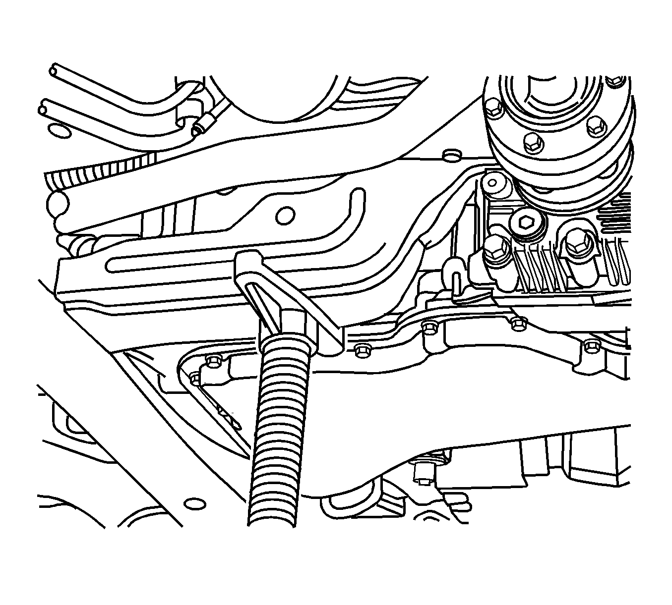
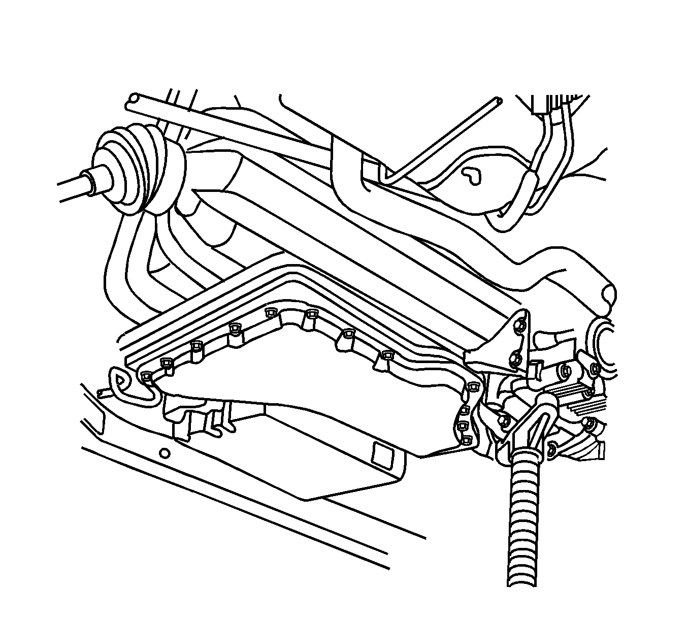

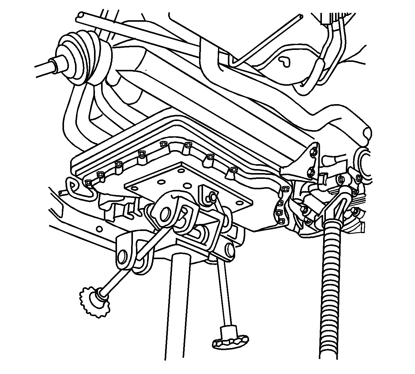
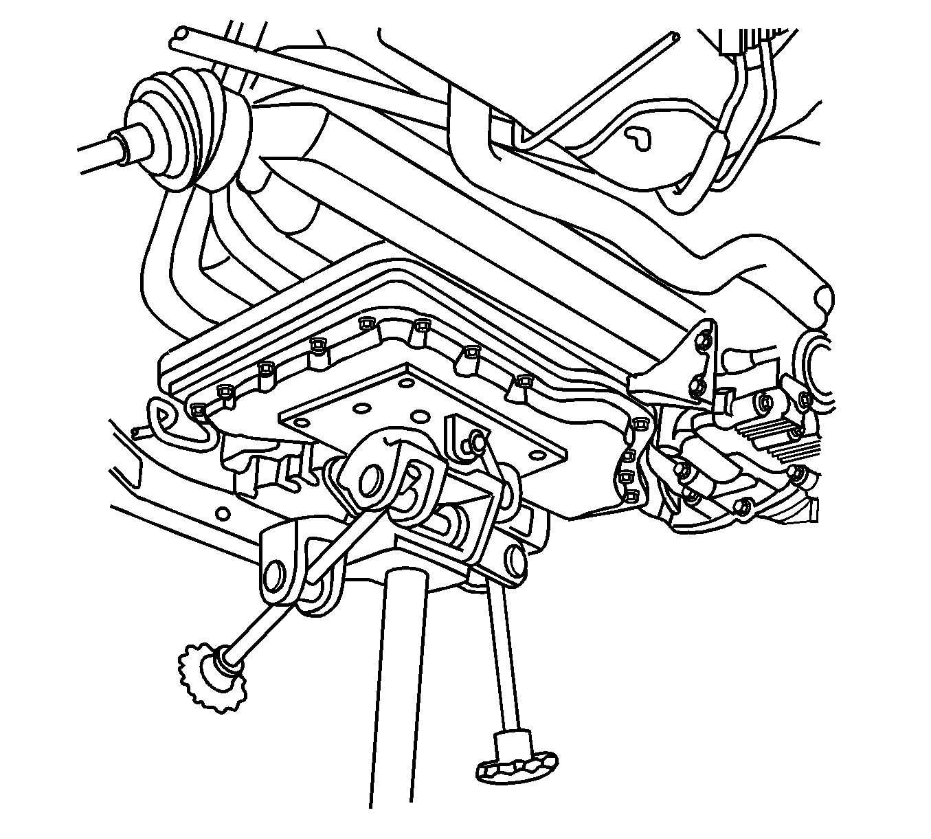
| 26.1. | Remove the frame insulators from the frame. Refer to Front Frame Cushion or Insulator Replacement . |
| 26.2. | Remove the lower control arms from the frame. Refer to Lower Control Arm Replacement in Front Suspension. |
| 26.3. | Remove the power steering cooler pipes from the frame. Refer to Power Steering Cooler Pipe/Hose Replacement in Power Steering System. |
Installation Procedure
- If you are REPLACING the frame, perform the following steps:
- Use a utility stand with the frame around it to support the powertrain.
- Remove the transmission stand from the powertrain.
- Install the frame to the vehicle.
- Use the utility stand to raise the frame and powertrain.
- Insert two 19 mm (0.75 in) diameter X 203 mm (8 in) long guide pins or drill bits into the frame right side alignment holes in order to align the frame.
- Install the frame to chassis front bolts.
- Install the frame to chassis rear bolts.
- Remove the alignment pins from the frame.
- Install the transaxle mount nuts.
- Install the engine mount nuts.
- Remove the utility stand from the powertrain.
- Use a utility stand to support the frame.
- Remove the rear frame bolts.
- Use the utility stand in order to lower the frame and powertrain.
- Connect the wheel speed sensor wiring harnesses to the lower control arms.
- Connect the wheel speed sensor harness connectors.
- Connect the lower control arms to the steering knuckles. Refer to Steering Knuckle Replacement in Front Suspension.
- Connect the power steering cooler pipe to the pressure hose. Refer to Power Steering Cooler Pipe/Hose Replacement in Power Steering System.
- Install front fender liner. Refer to Front Fender Liner Replacement in Exterior Trim.
- Install the power steering gear . Refer to Steering Gear Replacement in Power Steering System.
- Install the catalytic converter pipe. Refer to Catalytic Converter Replacement in Engine Exhaust.
- Install the propeller shaft. Refer to Propeller Shaft Replacement in Propeller Shaft.
- Install the stabilizer shaft. Refer to Stabilizer Shaft Replacement in Front Suspension.
- Install the front engine splash shield. Refer to Engine Splash Shield Replacement in Body Front End.
- Install the front tires and wheels. Refer to Tire and Wheel Removal and Installation in Tires and Wheels.
- Lower the vehicle.
- Remove the engine support fixture. Refer to Engine Support Fixture in Engine Mechanical - 3.4L.
| 1.1. | Install the power steering cooler pipes to the frame. Refer to Power Steering Cooler Pipe/Hose Replacement in Power Steering System. |
| 1.2. | Install the lower control arms to the frame. Refer to Lower Control Arm Replacement in Front Suspension. |
| 1.3. | Install the frame insulators to the frame. Refer to Front Frame Cushion or Insulator Replacement . |


Important: Ensure that the alignment pins remain installed during the frame installation.
Notice: Refer to Fastener Notice in the Preface section.

Tighten
Tighten the bolts to 155 N·m (114 lb ft).
Tighten
Tighten the bolts to 240 N·m (177 lb ft).
Tighten
Tighten the nuts to 47 N·m (35 lb ft).
Tighten
Tighten the nuts to 47 N·m (35 lb ft).

Front Frame Replacement w/FWD
Tools Required
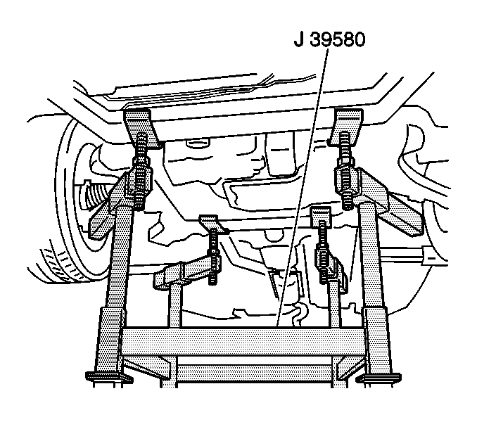
J 39580 Universal Engine Support Table
Removal Procedure
- Install the engine support fixture. Refer to Engine Support Fixture in Engine Mechanical - 3.4L.
- Raise and support the vehicle. Refer to Lifting and Jacking the Vehicle in General Information.
- Remove the front tires and wheels. Refer to Tire and Wheel Removal and Installation in Tires and Wheels.
- Remove the front engine splash shield. Refer to Engine Splash Shield Replacement in Body Front End.
- Remove the stabilizer shaft. Refer to Stabilizer Shaft Replacement in Front Suspension.
- Remove the power steering gear . Refer to Steering Gear Replacement in Power Steering System.
- Remove the inner fender liner enough to gain access to the front frame bolts. Refer to Front Fender Liner Replacement in Exterior Trim.
- Disconnect the power steering cooler pipe from the pressure hose. Refer to Power Steering Cooler Pipe/Hose Replacement in Power Steering System.
- Disconnect the front wheel speed sensor harness connectors.
- Disconnect the front wheel speed sensor wiring harnesses from the lower control arms.
- Disconnect the lower control arm from the steering knuckles. Refer to Steering Knuckle Replacement in Front Suspension.
- Remove the engine mount nuts.
- Remove the transaxle mount nuts.
- Lower the vehicle until the frame contacts the J 39580 .
- Remove frame to body bolts.
- Raise the vehicle in order to separate the frame from the vehicle.
- If you are REPLACING the frame, perform the following steps:

| 17.1. | Remove the frame insulators from the frame. Refer to Front Frame Cushion or Insulator Replacement . |
| 17.2. | Remove the lower control arms from the frame. Refer to Lower Control Arm Replacement in Front Suspension. |
| 17.3. | Remove the power steering cooler pipe from the frame. Refer to Power Steering Cooler Pipe/Hose Replacement in Power Steering System. |
Installation Procedure
- If you are REPLACING the frame, perform the following steps:
- Position the J 39580 with the frame under the vehicle.
- Lower the vehicle until the frame is close to the vehicle.
- Insert two 19 mm (0.75 in) diameter X 203 mm (8 in) long guide pins or drill bits into the frame right side alignment holes in order to align the frame.
- Install the frame to chassis front bolts.
- Install the frame to chassis rear bolts.
- Remove the alignment pins from the frame.
- Install the transaxle mount nuts.
- Install the engine mount nuts.
- Connect the lower control arms to the steering knuckles. Refer to Steering Knuckle Replacement in Front Suspension.
- Connect the wheel speed sensor wiring harnesses to the lower control arms.
- Connect the wheel speed sensor harness connectors.
- Connect the power steering cooler pipe to the pressure hose. Refer to Power Steering Cooler Pipe/Hose Replacement in Power Steering System.
- Install front fender liner. Refer to Front Fender Liner Replacement in Exterior Trim.
- Install the power steering gear . Refer to Steering Gear Replacement in Power Steering System.
- Install the stabilizer shaft. Refer to Stabilizer Shaft Replacement in Front Suspension.
- Install the front engine splash shield. Refer to Engine Splash Shield Replacement in Body Front End.
- Install the front tires and wheels. Refer to Tire and Wheel Removal and Installation in Tires and Wheels.
- Lower the vehicle.
- Remove the engine support fixture. Refer to Engine Support Fixture in Engine Mechanical - 3.4L.
| 1.1. | Install the power steering cooler pipe to the frame. Refer to Power Steering Cooler Pipe/Hose Replacement in Power Steering System. |
| 1.2. | Install the lower control arms to the frame. Refer to Lower Control Arm Replacement in Front Suspension. |
| 1.3. | Install the frame insulators to the frame. Refer to Front Frame Cushion or Insulator Replacement . |

Important: Ensure that the power steering cooler line does not become trapped by the engine mount during this step.
Important: Ensure that the alignment pins remain installed during the frame installation.
Notice: Refer to Fastener Notice in the Preface section.

Tighten
Tighten the bolts to 155 N·m (114 lb ft).
Tighten
Tighten the bolts to 240 N·m (177 lb ft).
Tighten
Tighten the nuts to 47 N·m (35 lb ft).
Tighten
Tighten the nuts to 47 N·m (35 lb ft).
