For 1990-2009 cars only
Removal Procedure
- Disable the SIR system. Refer to SIR Disabling and Enabling in SIR.
- Disconnect the negative battery cable. Refer to Battery Negative Cable Disconnection and Connection in Engine Electrical.
- Remove the quarter panel. Refer to Quarter Panel Replacement .
- Remove the roof panel. Refer to Roof Outer Replacement .
- Remove the center pillar. Refer to Center Pillar Replacement .
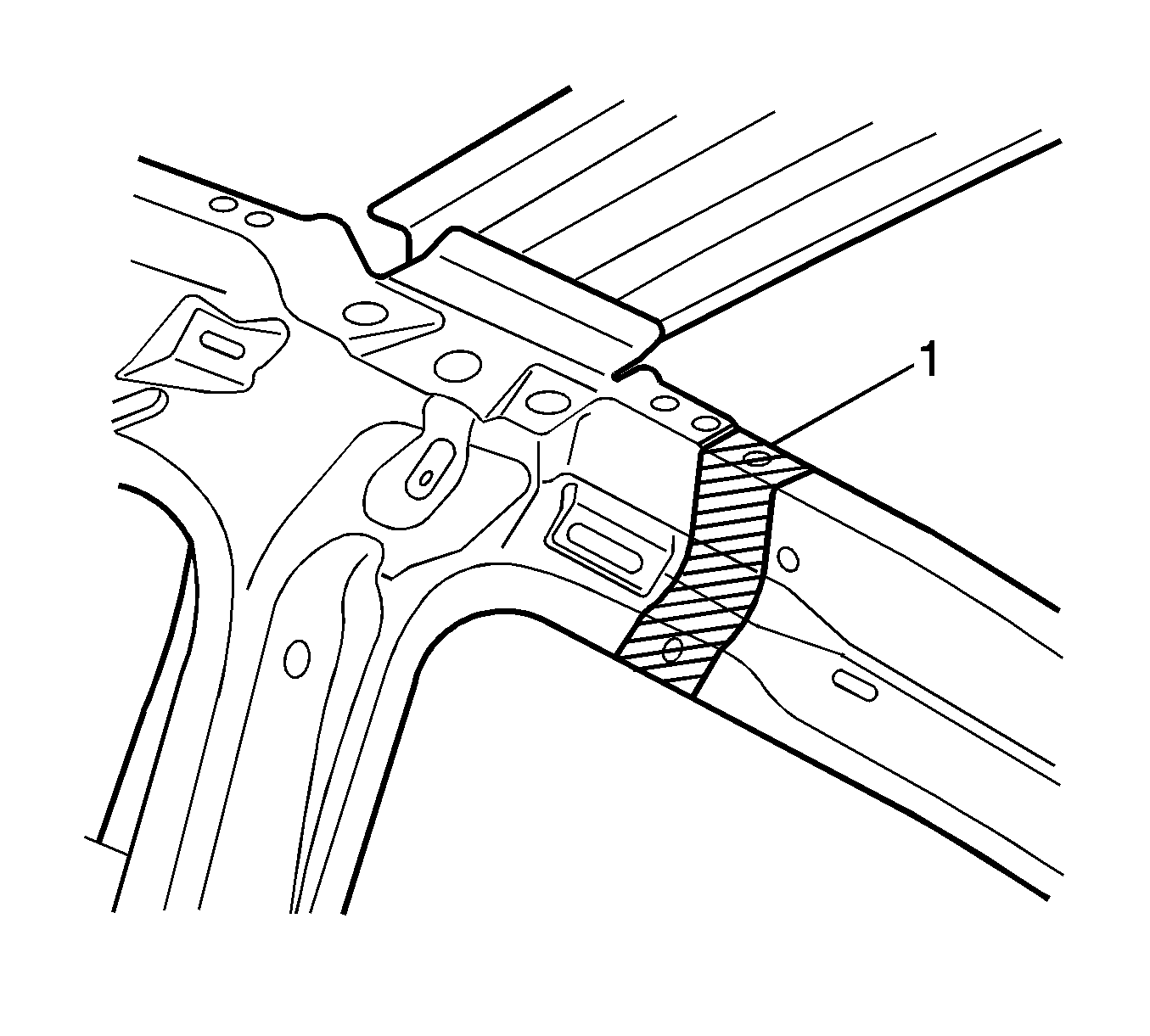
- Grind the mig welds (1) attaching the quarter panel wheelhouse assembly to the inner rocker panel.
- Remove all related panels and components.
- Restore as much of the damage as possible to factory specifications. Refer to Dimensions - Body .
- Note the location and remove the sealers and anti-corrosion materials from the repair area, as necessary. Refer to Anti-Corrosion Treatment and Repair in Paint/Coatings.
- Locate, mark, and drill out the welds attaching the wheelhouse panel to the rear floor pan assembly.
- Locate, mark, and drill out the welds attaching the rear window panel assembly to the rear seat back extension assembly.
- The center pillar inner panel assembly is attached to the wheelhouse assembly with plug welds and structural adhesive (1) GM P/N 12378567 (Canadian P/N 88901675 or Lord Fusor 108B).
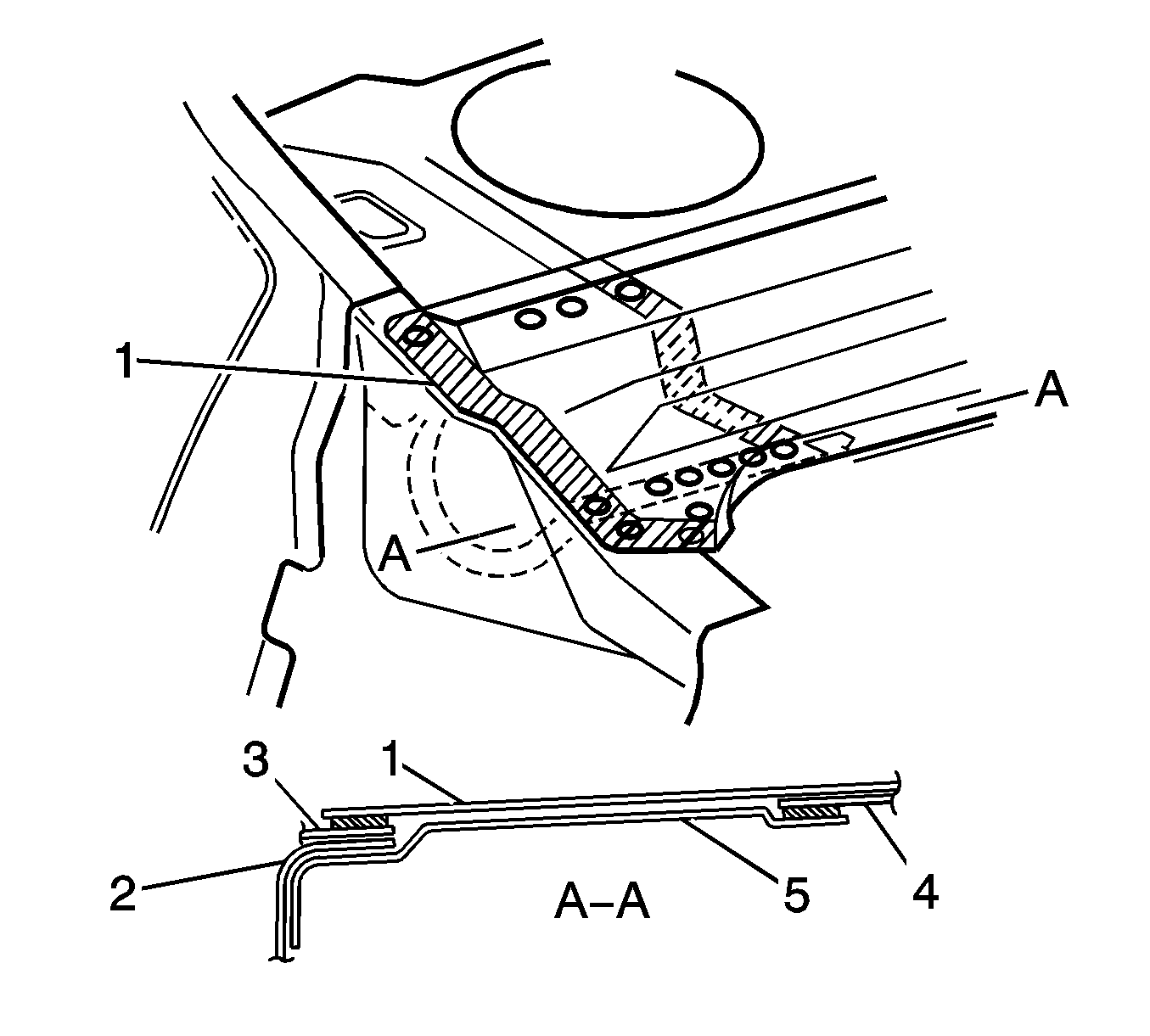
- Locate, mark, and drill out the welds attaching the rear window panel assembly (1) and (4) to the wheelhouse (3) and the rear seat back extension assembly (5).
- Remove the remaining flange of the rear quarter panel (3), leaving only the rear window panel assembly.
- Remove the damaged wheelhouse.
- Inspect and rectify the alignment of the body as required. Refer to Dimensions - Body .
Caution: Refer to Approved Equipment for Collision Repair Caution in the Preface section.


Caution: Refer to Foam Sound Deadeners Caution in the Preface section.
Important: Do not damage any inner panels or reinforcements.


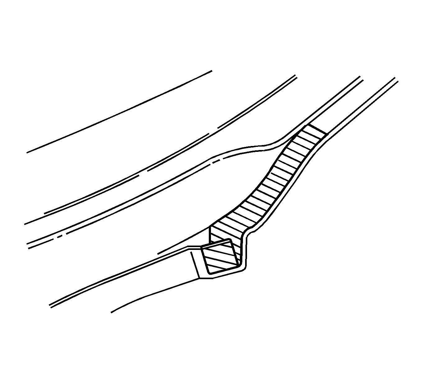
Important: Structural adhesive is applied in the areas shown shaded. As this material is extremely strong, the rear seat back extension assembly may require removing with a grinder.
Installation Procedure
- On the service part, drill 8-mm (5/16-in) plug weld holes every 40 mm (½ in).
- Prepare the mating surfaces.
- Apply 3M® Weld-Thru coating P/N 05916, or equivalent, to all of the mating surfaces.
- Apply structural adhesive GM P/N 12378567 (Canadian P/N 88901675 or Lord Fusor 108B) to the mating surface of the inner center pillar panel assembly (1).
- Apply structural adhesive GM P/N 12378567 (Canadian P/N 88901675 or Lord Fusor 108B) to the mating surface of the inner joint (1) of the rear seatback extension.
- Position the service part.
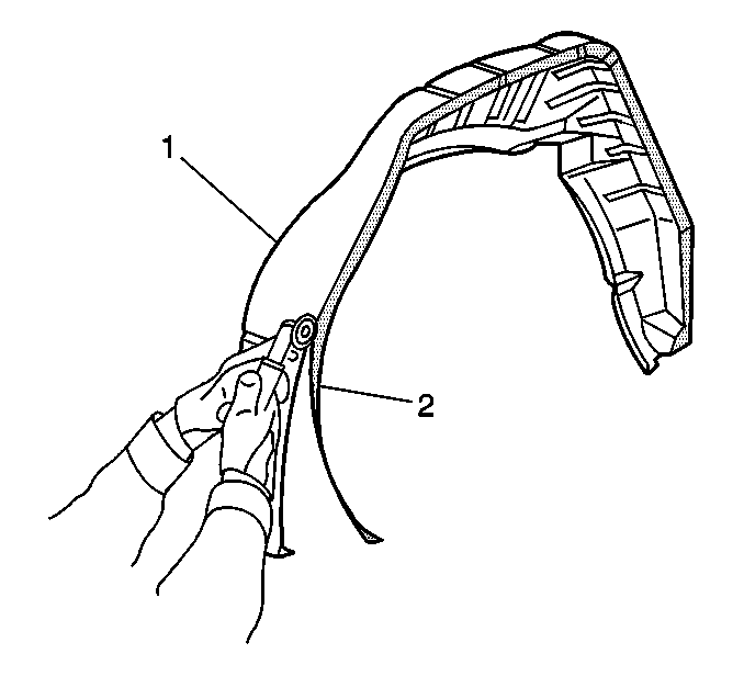
- Inspect for proper fit and plug weld accordingly (2). Take care not to warp or distort the metal.
- Mig weld (1) the wheelhouse assembly to the inner rocker panel.
- Clean up the welds as necessary.
- Apply the sealers and the anti-corrosion materials to the repair area, as necessary. Refer to Anti-Corrosion Treatment and Repair in Paint/Coatings.
- Install the center pillar. Refer to Center Pillar Replacement .
- Remove the roof panel. Refer to Roof Outer Replacement .
- Apply structural adhesive GM P/N 12378567 (Canadian P/N 88901675 or Lord Fusor 108B) to the mating surface of the quarter panel flange.
- Install the quarter panel. Refer to Quarter Panel Replacement .
- Apply the sealers and the anti-corrosion materials to the repair area, as necessary. Refer to Anti-Corrosion Treatment and Repair in Paint/Coatings.
- Paint the repair area. Refer to Basecoat/Clearcoat Paint Systems in Paint/Coatings.
- Install all related panels and components.
- Connect the negative battery cable. Refer to Battery Negative Cable Disconnection and Connection in Engine Electrical.
- Enable the SIR system. Refer to SIR Disabling and Enabling in SIR.


