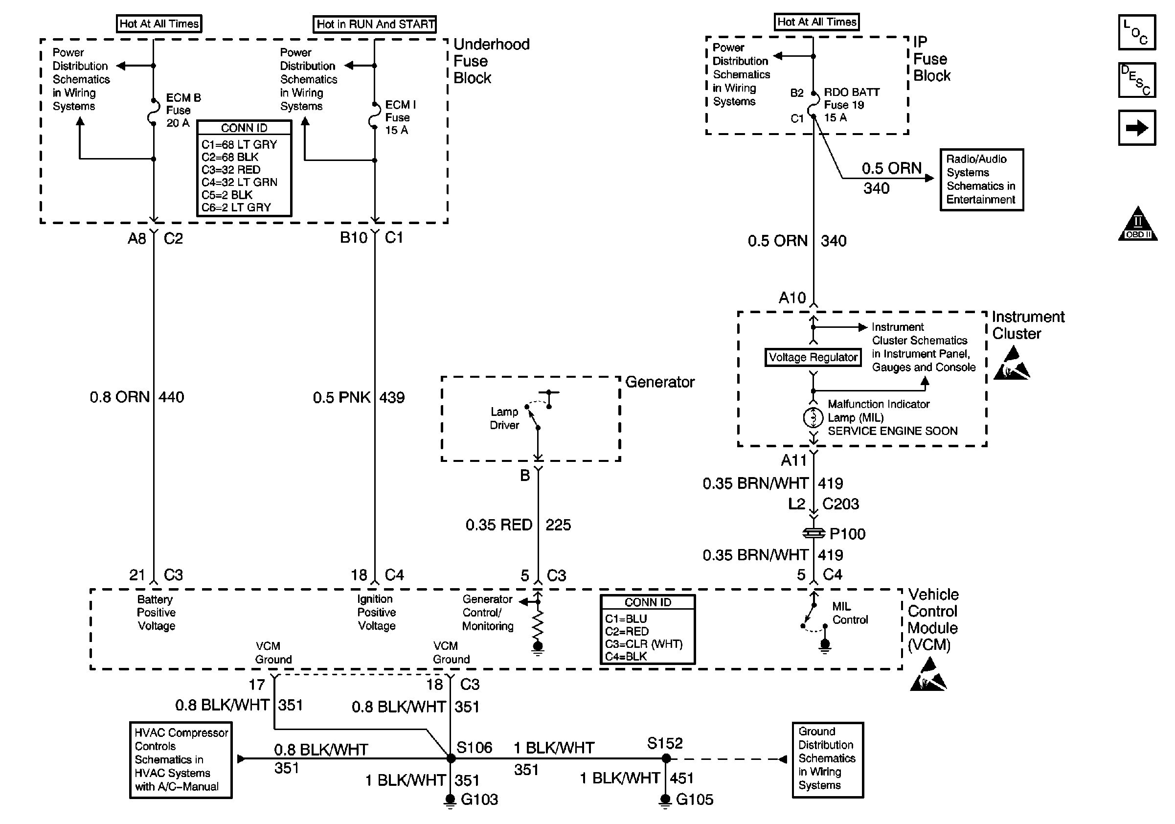
| Figure 1: |
ECM B, ECM I and RDO BATT Fuses, Ground, Generator and MIL
|
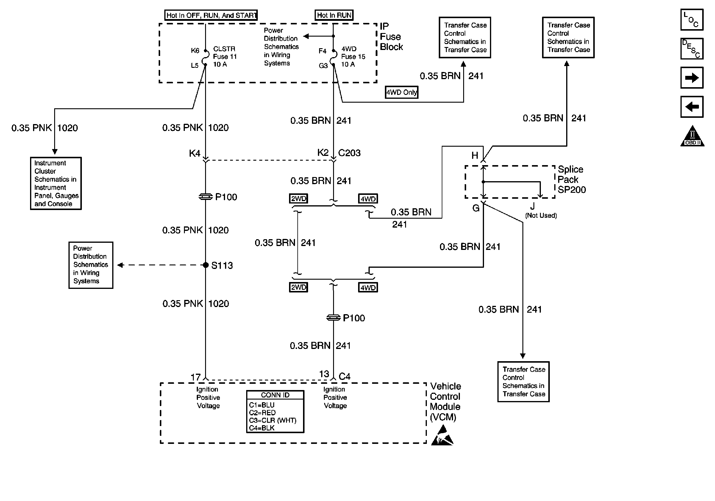
| Figure 2: |
VCM, CLSTR and 4WD Fuses
|
| Figure 3: |
Data Link Connector (DLC)

|
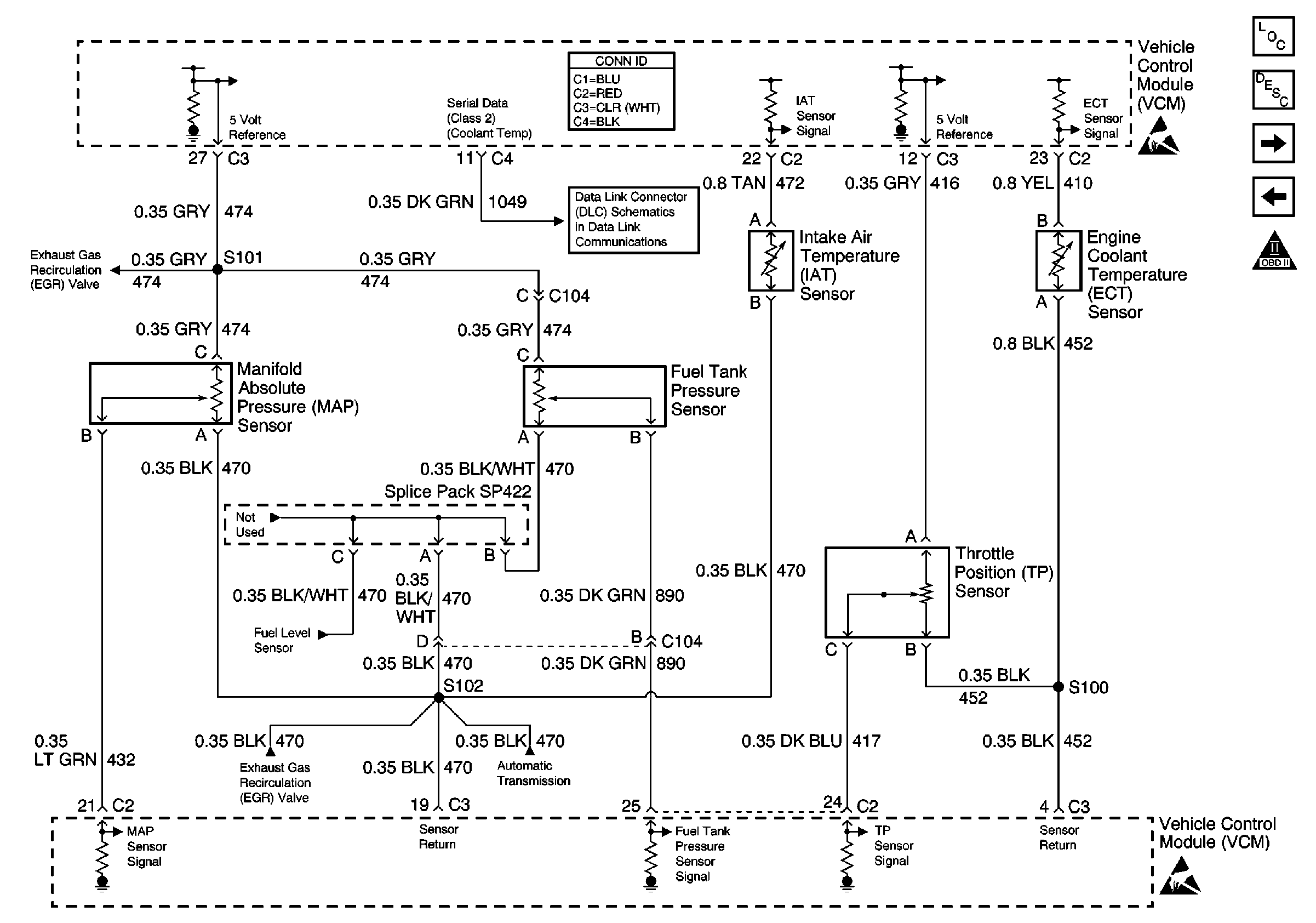
| Figure 4: |
Engine Sensors
|
| Figure 5: |
Heated Oxygen Sensors

|
| Figure 6: |
MAF Sensor and IAC Valve

|
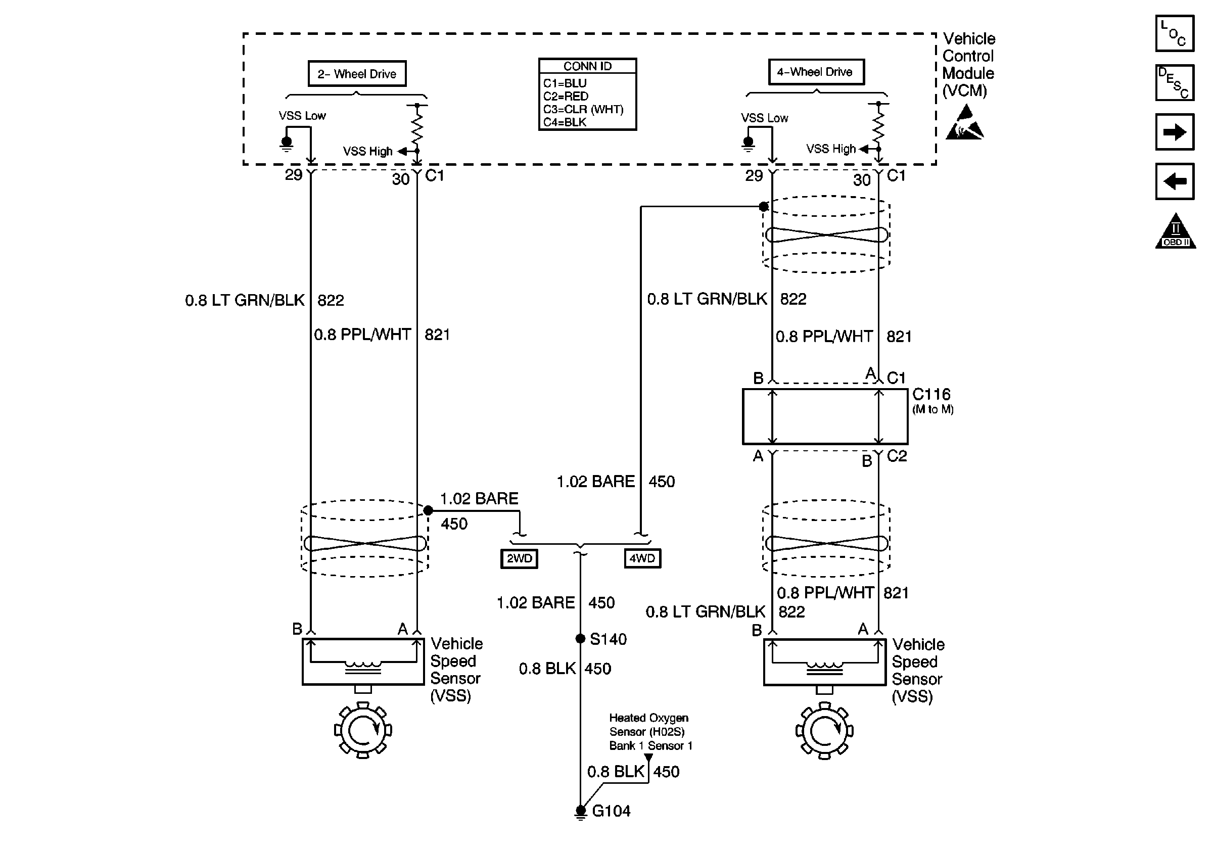
| Figure 7: |
Vehicle Speed Sensor (VSS)
|
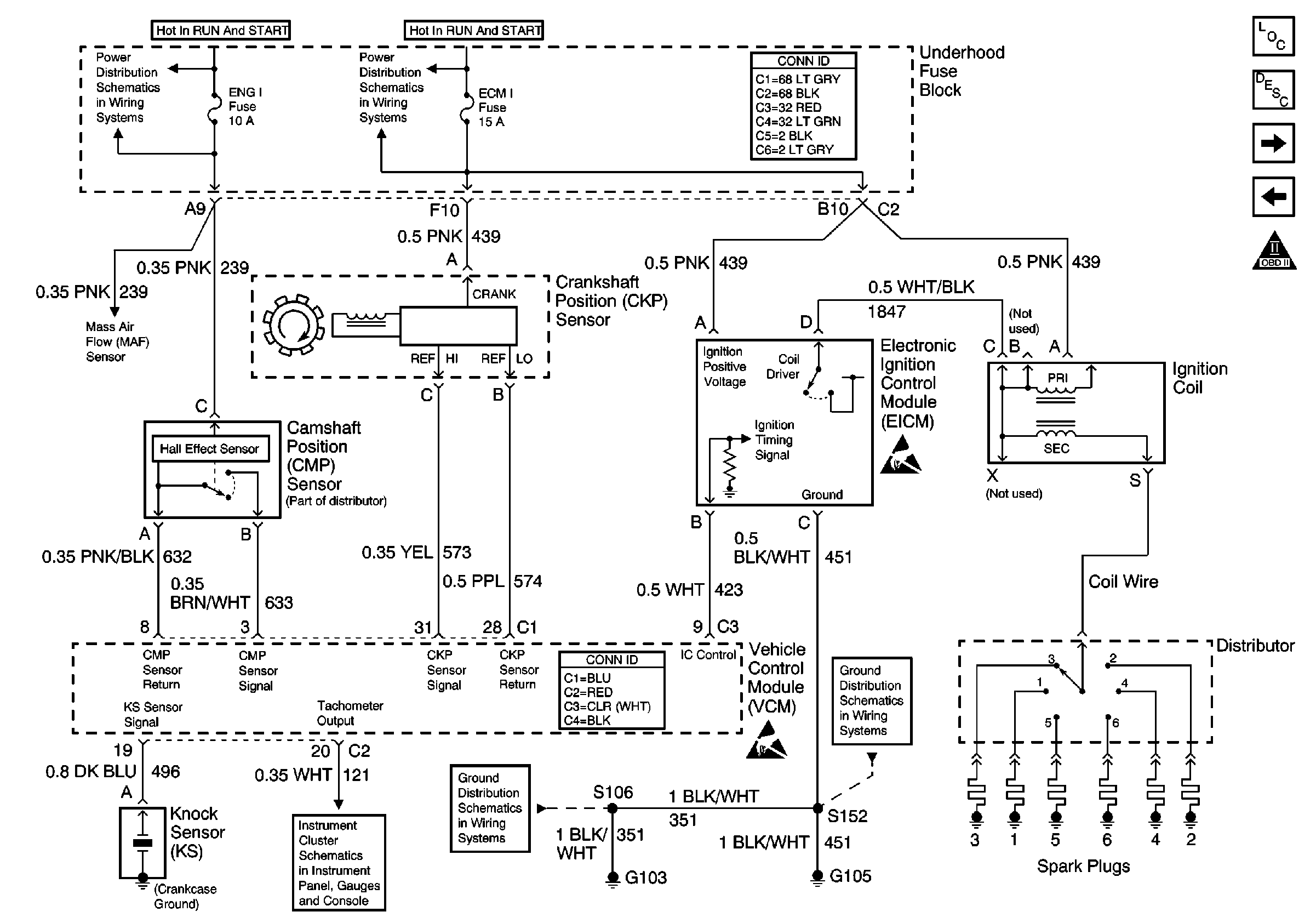
| Figure 8: |
Ignition Controls
|
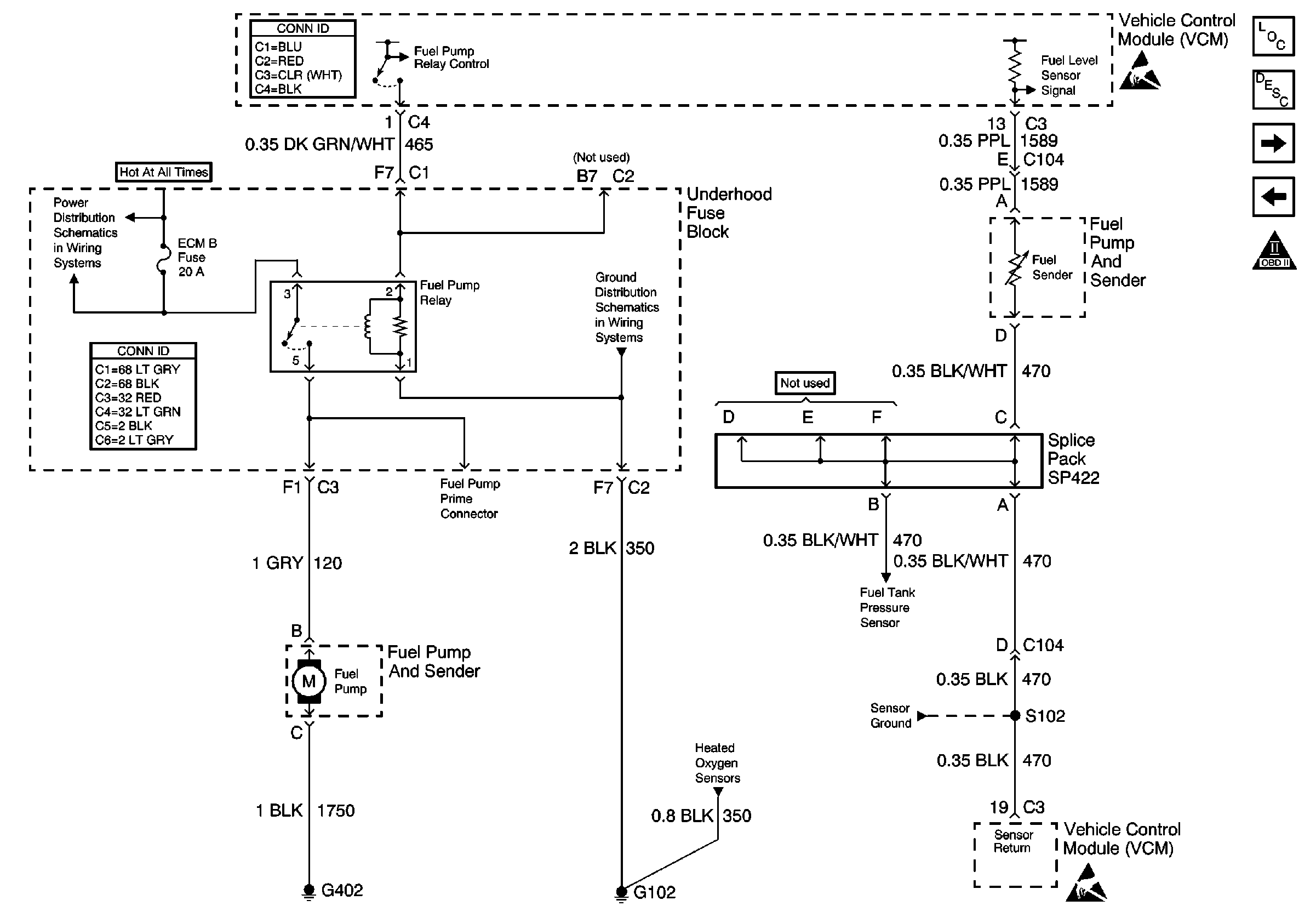
| Figure 9: |
Fuel Pump and Sender
|
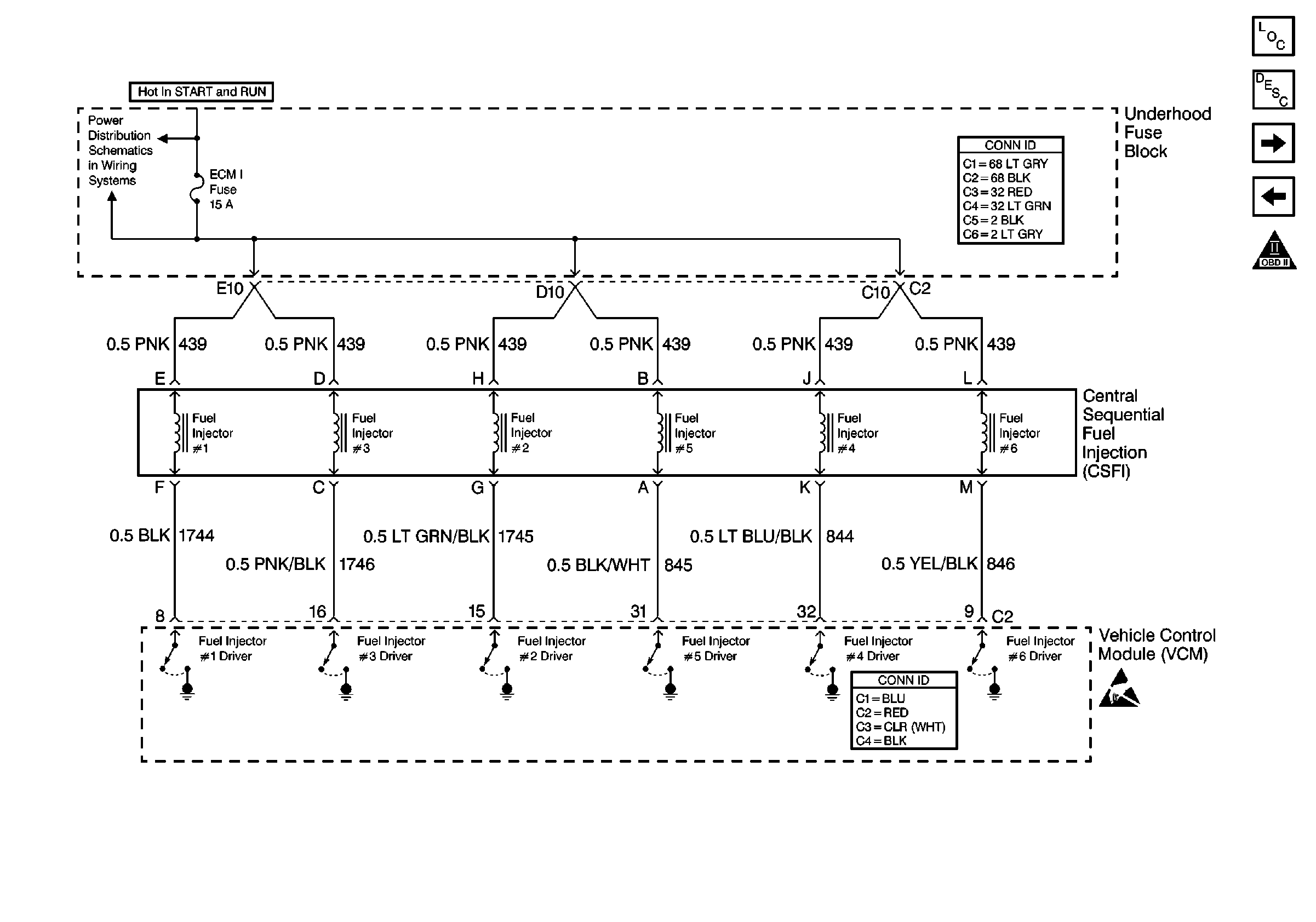
| Figure 10: |
Fuel Injection Controls
|
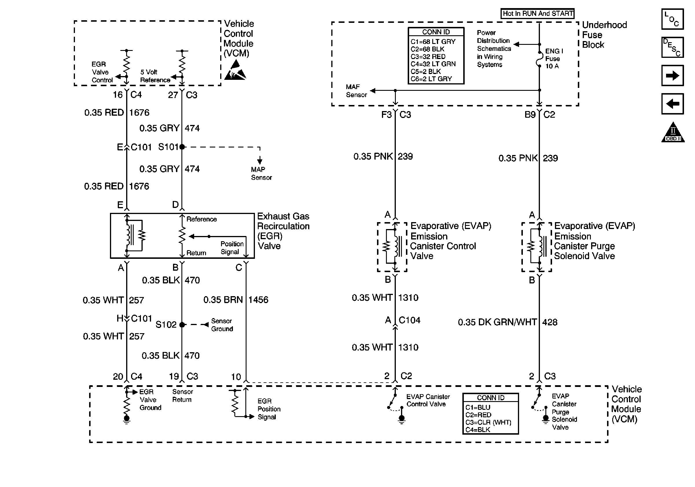
| Figure 11: |
EGR and EVAP Valves
|
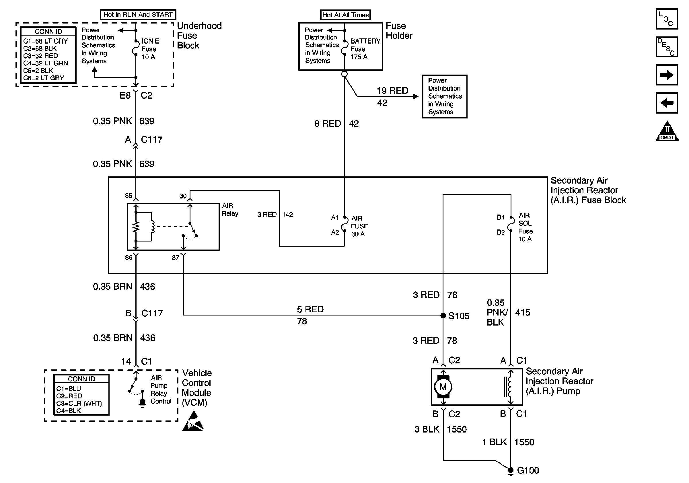
| Figure 12: |
Secondary AIR Pump Control
|
| Figure 13: |
A/C Compressor Control

|
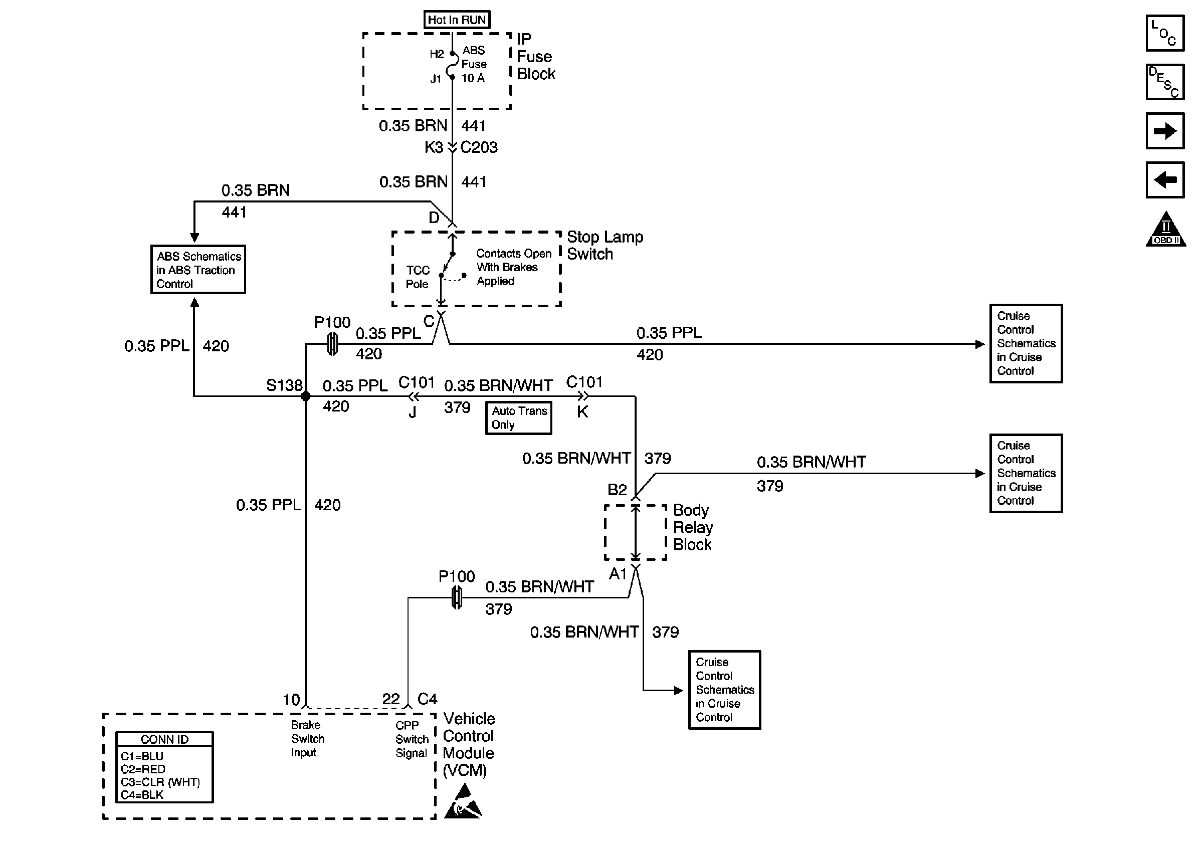
| Figure 14: |
Stoplamp Switch Input
|
| Figure 15: |
Vehicle Speed Outputs, 4WD High Indicator Signal, 4WD Indicator Switch

|
| Figure 16: |
Automatic Transmission Switch Inputs

|
| Figure 17: |
Automatic Transmission Valve Controls

|


